
rigid flex circuit assembly
Rigid-flex circuits offer advantages for a variety of electronic applications. Combining rigid and flexible circuits, they enable a streamlined design of complex products, while eliminating the need for multiple boards in an assembly. This reduces component weight and space, lowering the cost of manufacturing. In addition, rigid-flex PCBs are more reliable than traditional PCBs. This is due to the fact that signals do not need to travel across connectors, solder connections, and cable harnesses. This reduces points of failure in drop testing and other environmental stressors that could damage or break the product.
Rigid flex circuits are also lighter than individual rigid PCBs due to their thinner copper conductors. This is especially important for battery powered products and wearables, where every gram counts. This reduced weight and size also lowers the total system cost of the product, which can be a critical consideration for customers in the IoT, automotive, medical, and military industries.
A rigid flex circuits starts with a single or double-sided plated copper layer, which is typically planted using vapor deposition techniques and then laminated to an adhesive substrate such as polyimide or prepreg. The substrate is then cut to the size of the final PCB, and both the flex and rigid sections are drilled and etched in the same way that regular rigid PCBs are.
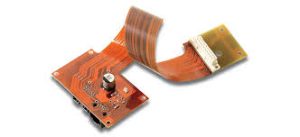
What role do adhesives play in rigid flex circuit assembly?
After etching the flex core, it is blanked into a final panel with borders for framing. This prevents the flex from separating from the rigid section during final assembly and reflow baking, and also provides a convenient mounting point for components. The edges of the flex core are typically protected by coverlay layers which act as an adhesive, though some designs may use an adhesive-less process in which a photo-imageable solder mask is printed directly onto the flex.
During the fabrication of a flex-rigid board, special adhesive fillets are used to provide additional support at the transition areas between the rigid and flex sections. These fillets help to distribute mechanical stresses, preventing delamination and separation between the different sections of the PCB during handling and bending operations.
These adhesive fillets are used in combination with the cladding layer to provide extra adhesion and mechanical strength. This helps ensure that the flex core stays securely attached to the rigid board sections and maintains connectivity and signal integrity throughout all operational environments.
The use of these specialized adhesives is an essential part of the production process, and is necessary to ensure that flex-rigid PCBs perform properly in the field. Thorough design validation tests and quality control measures including automated optical inspection (AOI) systems, impedance testing, thermal cycling analysis, and other reliability assessments all contribute to ensuring that the manufacturing process produces high-quality rigid-flex circuits. Ultimately, these rigorous quality control measures can mitigate issues with material selection, layer configurations, and bend radii compliance during production, reducing risks of assembly problems. This allows designers to focus on meeting their project’s requirements without compromising on performance or functionality.


