
Bend Radius For a Flexible Printed Circuit
When working with printed circuit boards, the minimum bend radius is an important factor to consider to ensure that the board can withstand its intended dynamic movements. While there are industry standards and guidelines to help determine the appropriate bending radius for a flexible PCB, it is also necessary to understand how to calculate this value for a specific board construction and application. This article will explore the basics of calculating the bend radius for a flex PCB, discuss the factors that can affect it, and provide some best practices for navigating this often complex issue.
In a static flex circuit design (sometimes referred to as a “Flex to Install” flex PCB), the flex board is bent/creased only once to be installed in an assembly. This type of flex circuit typically has a minimum bend radius that is approximately six times the thickness of the flex layer. In a dynamic flex circuit, the flex board is repeatedly bent/creased over its lifespan. This type of flex circuit requires that the minimum bend radius be substantially larger, ranging between 10 and 12 times the flex thickness for more complex multi-layer constructions.
The bending radius of a flexible printed circuit is determined by a combination of factors, including the thickness of the flex layer and the number of layers. Thicker flex circuits have greater rigidity, and thus require a larger bending radius than thinner ones. Additionally, the type of copper used in a flex circuit, as well as its thickness and distribution, will impact the required bending radius.
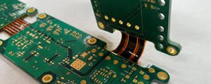
Calculating the Bend Radius For a Flexible Printed Circuit
To avoid damage to the conductive elements during bending, it is crucial that the correct bending radius be calculated and adhered to. This can be done by following one of several standard methodologies, depending on the bending method and flex PCB material. One of the most common methods is to follow IPC-223 standards, which provides general guidelines for calculating the bending radius based on the flex PCB’s thickness and construction.
One of the primary advantages of flexible printed circuits is their ability to withstand mechanical stress and environmental factors that would compromise traditional rigid PCBs. The flexibility of FPCs makes them highly resilient to shock and vibration, making them ideal for use in applications where durability is paramount. Furthermore, FPCs exhibit excellent thermal stability, ensuring reliable performance even in challenging operating conditions.
When designing a flex circuit, the correct bending radius should be considered at all stages of the design process. This includes the initial layout, as well as the routing and placement of components, traces, and vias. Keeping these areas away from critical bending areas can help prevent stress concentrations and increase the longevity of the flex circuit. In addition, adding alignment features like notches or registration marks to the flex circuit can help assemblers align the board properly and avoid overstressing the bending zones. Finally, it is recommended that a stiffener be added to critical bending areas to increase their mechanical durability.

